More Netduino fun
 Last time, we ran a very simple program on the Netduino. This time around, we’ll actually connect some real hardware to that microcontroller and blink some lights! You know what? Let’s go crazy! Let’s go for Knight Rider lights! Woohoo!
Ahem.
Yeah. Well, you’ve got to start small. Anyway, I have this LED array that I’m going to build a little something on soon. This time, we’ll just use a single line for that simple effect.
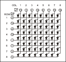
The LED array can be found here: http://futurlec.com/LEDMatrix.shtml for $1.80, which is ridiculous. It’s the LEDMS88R. A LED array is a very simple piece of hardware: it’s just LEDs at each intersection of line and column wires:
To turn on one of the LEDs, just send some juice between the right line and column. You can even turn on an arbitrary combination of lights on any line or any column. But of course if you try to do any more than that, you’ll have extra pixels lit in most cases. What you do instead is use persistence of vision and scan the matrix line by line very fast. This way you can display any 8x8 image at all. But today, we only need a single line.
Before we connect the controller to the matrix though, we need to deal with a small problem that will be very common as we build more hardware prototypes. Before you use any component at all, you need to RTFM. Let me repeat that:
You need to READ THE EFFING MANUAL.
For real. I know you’re a super geek and make a point of never ever doing that. Well, hardware is not like software. The equivalent of an API, for hardware, is the pin repartition but it doesn’t have names, it doesn’t have comments, and it’s not designed to be logical.
Just take another look at that LED matrix schema above. Notice anything? Yes, pin number 1 is for row 5, pin 2 is for row 7, pin 3 is for column 2, and so on until your sanity’s just a confused and fading memory. You don’t want to have to figure this out by trial and error. Just read the damn thing.
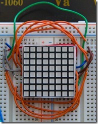
In order to get halfway back from that dark pit of madness, we’ll have to build a rational façade of sorts before that matrix. That façade can be either software on the microcontroller or it can be hardware. I opted for hardware, which I think deals with the problem once and for all and allows for more flexibility in design going forward. I went ahead and mapped the pins of the matrix to the rows 1 to 8 of two columns on my breadboard, one for rows and one for columns:
One thing I might do eventually is to order a custom circuit that hosts the matrix, does the mapping and is easy to plug into the breadboard: those wires are ugly.
Another thing to keep in mind is that the consequences of a hardware mistake is not going to be a nice exception. There will be smoke. You’re going to fry a chip, or your microcontroller, or both. All the more reason to READ THE EFFING MANUAL. And check everything ten times before you switch on the power. Oh wait, make it twelve.
For example, when getting current flowing through LEDs like those in that matrix, remember a passing LED is like a wire, so it’ll short-circuit if you don’t put a resistor in front of it. If the LED doesn't fry before, which it will. But you don't want to use LED matrices as fuses.
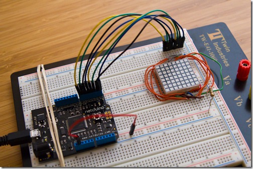
For our Knight Rider effect, we only need one line, so I connected the 3V power line of the Netduino to one of the + columns of the breadboard. I then pulled a 150 Ohms resistor between that and the column 1 of the matrix. Then I pulled a wire between the pins for each row and the digital ports 0 to 7 of the Netduino:
Now all we have to do is write the small bit of code that will turn the LEDs on and off in the right order:
using System.Threading;
using Microsoft.SPOT.Hardware;
using SecretLabs.NETMF.Hardware.Netduino;

namespace HelloNetduino {
    public class Program {
        private static readonly OutputPort[]
          ColPorts = new [] {
            new OutputPort(Pins.GPIO_PIN_D0, false),
            new OutputPort(Pins.GPIO_PIN_D1, false),
            new OutputPort(Pins.GPIO_PIN_D2, false),
            new OutputPort(Pins.GPIO_PIN_D3, false),
            new OutputPort(Pins.GPIO_PIN_D4, false),
            new OutputPort(Pins.GPIO_PIN_D5, false),
            new OutputPort(Pins.GPIO_PIN_D6, false),
            new OutputPort(Pins.GPIO_PIN_D7, false)
        };

        public static void Main() {
            var switchPort = new InputPort(
                Pins.ONBOARD_SW1,
                false,
                Port.ResistorMode.Disabled);
            var dir = 1;
            var i = 0;
            while (switchPort.Read()) {
                for (; i >= 0 && i < 8 &&
                       switchPort.Read(); i+= dir) {
                    ColPorts[i].Write(false);
                    Thread.Sleep(50);
                    ColPorts[i].Write(true);
                }
                dir *= -1;
                i += dir;
            }
        }
    }
}
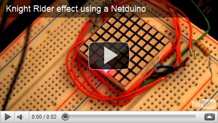
Now that wasn’t too hard. Here’s the result:
Next time, I’ll really give that shopping list I promised last time, and we’re going to see how to address any of the 8 rows and 8 columns on the matrix even though the Netduino only has 14 digital ports.
