Improving the Netduino Knight Rider effect with a shift register
 In my last Netduino post, I showed how to create a simple Knight Rider effect. One of the problems of that implementation was that we were occupying one digital port of the Netduino for each light in the ramp. It’s fine for that simple effect, but in future posts we’ll look at controlling our whole 8x8 LED matrix, which has 16 pins whereas the Netduino has only 14 digital ports.
In order to address all the matrix pins, we will need to do some multiplexing. Multiplexing means trading some time for some space. In our case, instead of using 8 parallel ports for each of the LEDs that we want to address, we’ll stream the 8 bits onto a single port serially in time and have a special component spread that onto the matrix’s pins.
This can be very simply done using a SN74HC595 shift register. These little chips come for less than a dollar and are fairly easy to use.

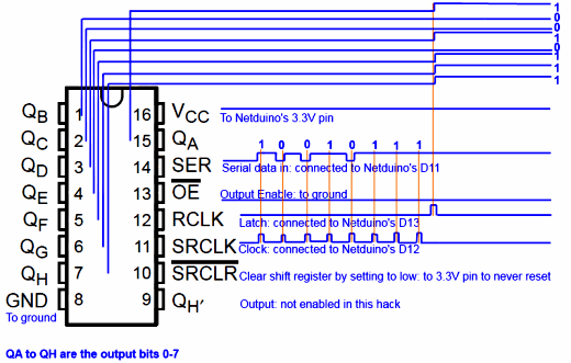
As you can see from the diagram above, you need to send the bits in sync with the clock, and once you’re done, trigger the latch to tell the shift register you’re done transmitting. The output pins then reflect spatially the sequence of bits that was serially input.
Here is the code that would produce that result on the shift register:
byte value = 0x97; // 10010111
Latch.Write(false);
// Lower Clock
Clock.Write(false);

for (var i = 0; i < 8; i++) {
    byte mask = 1;
    mask <<= 7 - i;

    var pinState = (mask & value) != 0;

    // Write data bit
    Data.Write(pinState);

    // Pulse Clock
    Clock.Write(true);

    // Raise Data to prevent IO conflict
    Data.Write(true);

    Clock.Write(false);
}

// Set the latch high to indicate that
// we're done transmitting
Latch.Write(true);
Latch.Write(false);
This time, the data we have to feed into the shift register will be very simple: we just want one bit at a time that we’re going to shift back and forth.
var button = new InputPort(
                   Pins.ONBOARD_SW1, false,
                   Port.ResistorMode.Disabled);
var sr = new ShiftRegister74HC595(
               1, DataPin, Clock, Latch,
               Pins.GPIO_NONE);
var dir = 1;
var i = 0;
while (button.Read()) {
    for (; i >= 0 && i < 8; i += dir) {
        sr.Write((byte)(1 << i));
        Thread.Sleep(50);
    }
    dir *= -1;
    i += dir;
}
We are using a little abstraction class around the shift register here (written by Fabien) that has a Write method that takes a byte and sends it to the SN74HC595.
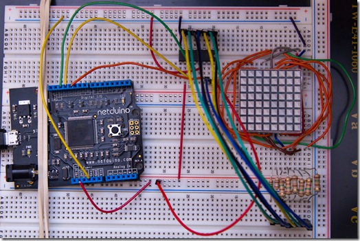
The wiring for this is pretty straightforward.
The first row of the LED matrix is wired to the ground so that the sequence displays on that row only. The outputs of the shift register go to the columns of the LED matrix through 8 150Ω resistors.
Here’s a video of the result:
Next time, we’ll get a full 8x8 image to display on the LED matrix.
You can download the code for this project here:
NetduinoKnightRiderShiftRegister.zip
Oh, and one last thing… I’ve been promising a shopping list for beginners, and Fabien was kind and patient enough to write this great post:
http://fabienroyer.wordpress.com/2010/11/11/where-to-find-parts-for-your-netduino/
