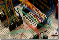
Driving a LED matrix from a Netduino one more time: The Right Way
 In previous posts, we've seen two ways one can drive a small LED matrix from a Netduino.
The first time, we just turned the rows and columns of the matrix on and off using digital ports on the Netduino. With this method, we have great control for sure, but it's no good for the following reasons.
It's very slow: the digital ports on the microcontroller don't switch very fast.
What kills it though is that we don't have enough digital ports on the Netduino: for an 8x8 matrix, you would need 16 ports and we only have 14. not to mention the final system we're building will need some ports for other things than display.
With the second and third posts, we used a shift register. The way you talk to a shift register is that you send it data on a serial channel and it will dispatch that data to its output ports. In other words, it trades ports for time, effectively demultiplexing data and multiplying the number of available ports.
The rows in this version were still addressed by individual digital ports on the Netduino. We would scan each line in turn and send the columns to light up for that line to the shift register. Do it fast enough and persistence of vision will make you see a relatively stable image.
This worked well enough, and we wrote some interesting drawing APIs for it, but as we started asking the Netduino to handle more than refreshing the display, we started to see frames drop.
The whole thing was a very useful learning experience, going from the lowest-level way to drive things, to what we're going to do today, which is quite more abstracted than what we started with, but performs admirably.
The solution we settled for, which is clearly The Right Way, is to use a LED driver such as a Maxim 7219 or 7221. Those neat little chips come for ten dollars a piece, which is not cheap, but they are worth every cent.
Those LED drivers do one thing and do it really well: send them data over the serial channel and let them deal with the rest. The driver we picked knows how to drive a 8x8 matrix so all you have to do is send it eight bytes of data every time you want to change what's displayed.
There is a little protocol to deal with as the chip has commands to send data but also commands for setting the display intensity or the display mode but nothing outlandish. In fact, using the driver enabled us to remove most of the low-level display code we were using.
For example, here is the code we need in order to send a screenful of data:
public void Display(byte[] matrix) {
    if (matrix.Length != 8) {
        throw new ArgumentOutOfRangeException("matrix");
    }
    var rowNumber = (byte)RegisterAddressMap.Digit0;
    foreach (var rowData in matrix) {
        Write(rowNumber, rowData);
        rowNumber++;
    }
}
It doesn't get any simpler than that. And it's screaming fast. Almost all of the processing power of the microcontroller can now be used to other tasks than managing the display.
We did hit a few bumps on our way there. The one that got us to scratch our heads in puzzlement the longest was that we noticed that after a while, our driver started to only display parts of the picture.
That was troubling because the driver has a command that does exactly that: crop the display to a fixed number of lines. But here's the thing: we were never calling that command. At all.
This is where hardware requires a lot more experimental method than software: you have to consider every possibility, even unknown failures and random deviations from the spec.
What we did to find what was going wrong is that we looked at the binary codes for the commands we were sending and compared them with the code for the ghost command that was seemingly arriving to the driver. We found that the command to set the intensity of the display was differing by only one bit. Somewhere along the way, that bit was getting lost, one time out of several thousand. But as the cropping command is lasting, the effect of a small error was persisting until the next error. Like a mutation.
Once we determined that and proved that this was effectively what was happening by trying the same demo without the intensity command, we still had to find what was losing the bit. We did that by isolating variables, like one should but we got lucky as the first thing we tried was it.
It happened that we had a small circuit between the Netduino and the Maxim that we added because the Netduino's ports are 3.3V and the Maxim is accepting 5V, with a minimum specified of 3.5V. That circuit is a logic level converter that just takes care of converting digital signals from one voltage to another. Well, it seems like once in a rare while, it loses some bits.
We removed the circuit and tried to see if the Maxim would be OK with 3.3V. Both of those we tried were quite happy with it.
You can follow our progress on our Codeplex project:
http://netduinohelpers.codeplex.com/
Fabien has some more details about using the Maxim driver:
http://fabienroyer.wordpress.com/2011/03/13/using-a-max7219max7221-led-display-driver-with-a-netduino/